
LMEC-7 Pohl’s Pendulum
LMEC-7 Pohl’s Pendulum
Experiments
1.Free oscillation – measurement of the correspondence between the amplitude of the balance wheel θ and the period of free oscillation T
2.Determination of the damping factor β.
3.Determination of the amplitude-frequency characteristic and the phase-frequency characteristic curves of forced vibrations.
4.Study of the effect of different damping on forced vibrations and observation of resonance phenomena.
5.Learn to use the stroboscopic method to determine certain quantities of moving objects, such as phase differences.
Main Specifications
| Spring stubbornness factor K | less than 2% change in free vibration period |
| Time measurement | accuracy 0.001s, cycle measurement error 0.2% |
| Mechanical pendulum | with indexing slots, indexing 2°, radius 100 mm |
| Amplitude measurement | error ±1° |
| Photoelectric sensor A | detection of double photoelectric signals |
| photoelectric sensor B | detection of single photoelectric signals |
| Motor speed (forcing frequency) range | 30 – 45 rpm and continuously adjustable |
| Motor speed instability | less than 0.05%, ensuring a stable test cycle |
| System damping | less than 2° per amplitude decay |
Details
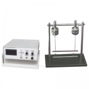
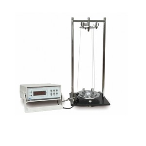
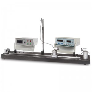
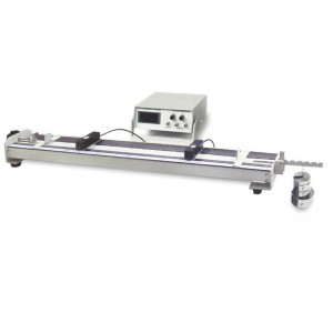
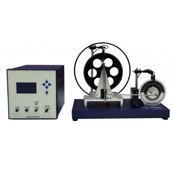
System components: Pohl resonance experimental device, Pohl resonance experimental controller, separate flash assembly, 2 photoelectric sensors (one each of type A and type B)
Pohl resonance experimental set-up.
1. Spring stubbornness factor K: less than 2% change in free vibration period.
2. Time measurement (10 cycles): accuracy 0.001s, cycle measurement error 0.2%.
3. System damping in the absence of electromagnetic damping: less than 2° per amplitude decay.
4. Mechanical pendulum: with indexing slots, indexing 2°, radius 100 mm.
5. Amplitude measurement: error ±1°; amplitude measurement method: photoelectric detection.
6. Photoelectric sensor A: detection of double photoelectric signals; photoelectric sensor B: detection of single photoelectric signals.
7. Motor speed (forcing frequency) range: 30 – 45 rpm and continuously adjustable.
8. Motor speed instability: less than 0.05%, ensuring a stable test cycle.
9. Phase difference determination.
Two methods of phase difference determination: stroboscopic and metrological, with a deviation of less than 3° between the two methods.
The measurement range of the metrological method is between 50° and 160°.
Stroboscopic measurement range between 0° and 180°; repeated measurement deviation <2°.
10. Flash: low voltage drive, flash separate from the experimental unit, 2ms continuous flash time, colour eye-catching red.
11. Low noise, no disturbance or discomfort during group experiments.
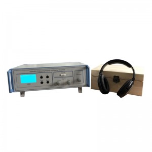
Pohl resonance experimental controller.
1. A special experimental controller is used to collect and display data; a large dot-matrix LCD display is used, with menus to guide the experiment, prompting notes (electronic instruction manual), and displaying and checking back experimental data.
2. Dedicated control interface for strobes.