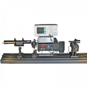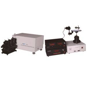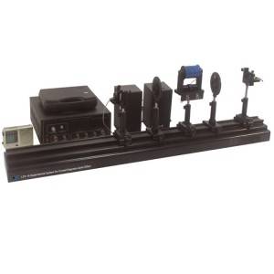

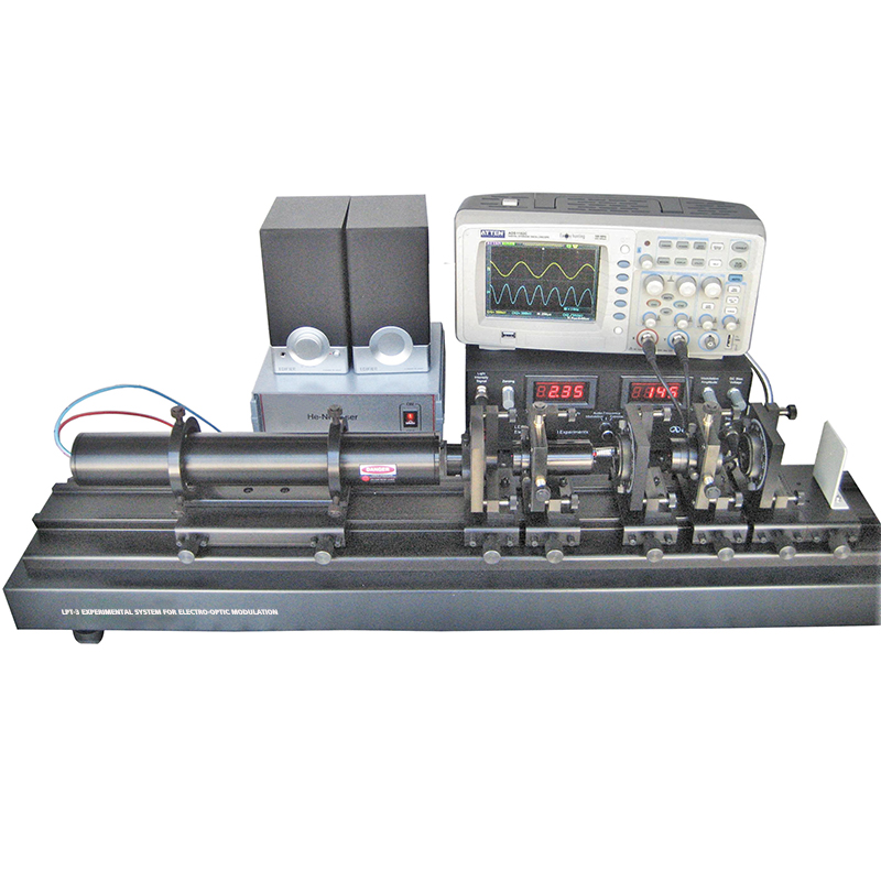
LPT-3 Experimental System for Electro-Optic Modulation
Experiment Examples
1. Display electro-optic modulation waveform
2. Observe electro-optic modulation phenomenon
3. Measure half-wave voltage of an electro-optic crystal
4. Calculate electro-optic coefficient
5. Demonstrate optical communication using electro-optic modulation technique
Specifications
| Power Supply for Electro-Optic Modulation | |
| Output Sine-Wave Modulation Amplitude | 0 ~ 300 V (Continuously Adjustable) |
| DC Offset Voltage Output | 0 ~ 600 V (Continuously Adjustable) |
| Output Frequency | 1 kHz |
| Electro-Optic Crystal (LiNbO3) | |
| Dimension | 5×2.5×60 mm |
| Electrodes | Silver Coating |
| Flatness | < λ/8 @633 nm |
| Transparent Wavelength Range | 420 ~ 5200 nm |
| He-Ne Laser | 1.0 ~ 1.5 mW @ 632.8 nm |
| Rotary Polarizer | Minimum Reading Scale: 1° |
| Photoreceiver | PIN Photocell |
Part List
| Description | Qty |
| Optical Rail | 1 |
| Electro-Optic Modulation Controller | 1 |
| Photoreceiver | 1 |
| He-Ne Laser | 1 |
| Laser Holder | 1 |
| LiNbO3 Crystal | 1 |
| BNC Cable | 2 |
| Four-Axis Adjustable Holder | 2 |
| Rotary Holder | 3 |
| Polarizer | 1 |
| Glan Prism | 1 |
| Quarter-Wave Plate | 1 |
| Alignment Aperture | 1 |
| Speaker | 1 |
| Ground Glass Screen | 1 |
Write your message here and send it to us